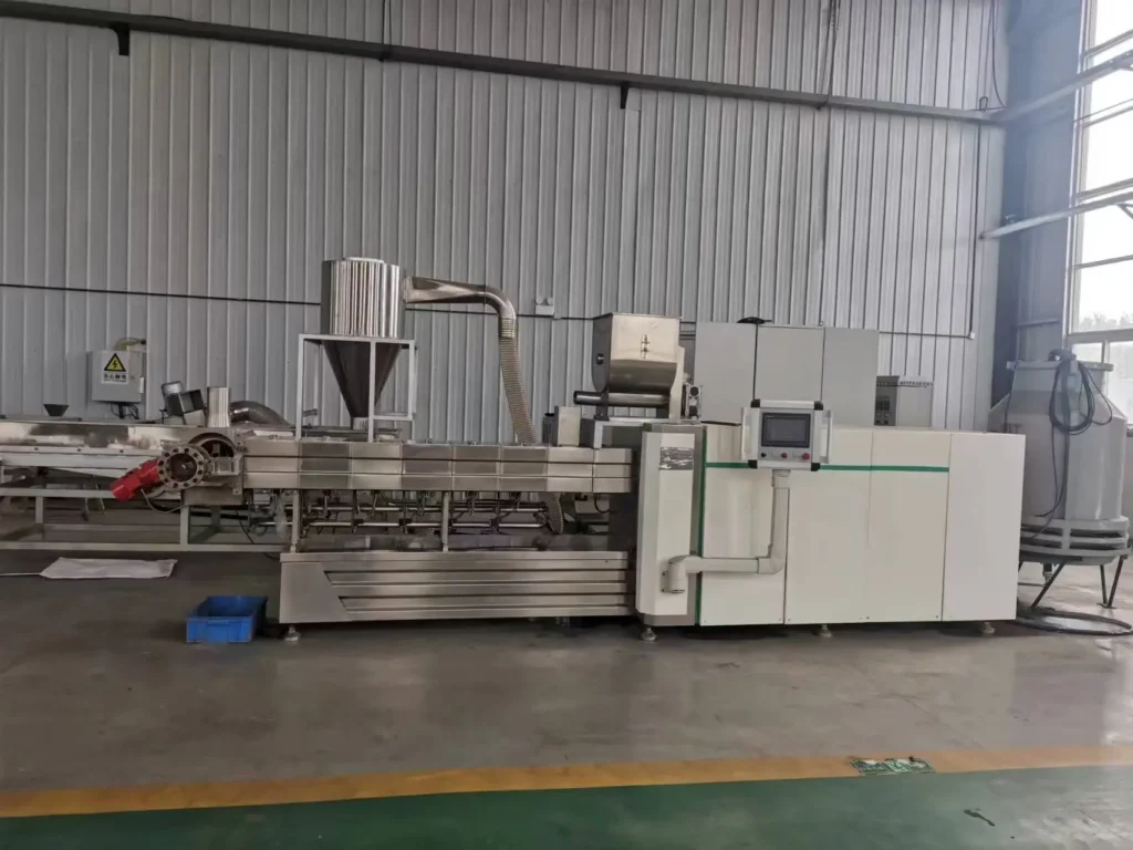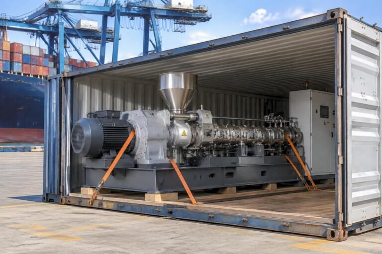
Maximizing container space to save freight costs is the fastest way to destroy a complete extrusion line before it even reaches your factory.
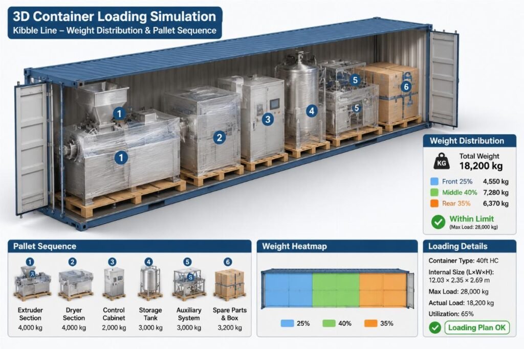
Shipping a complete kibble line requires precise 3D container loading plans and sequential palletizing to prevent transit damage, ensure weight balance, and guarantee that the unboxing sequence perfectly matches your on-site installation flow.
Years ago, at a pet food trade show in Chicago, I finalized a deal with a client from Texas for a mid-scale capacity pet food production line. An old-school master taught me to dismantle the dryer modules and wedge them tightly into a 40ft HC container. When the cargo arrived at the port, the client insisted on unloading it themselves. Because the pallets were not stacked according to the disassembly and assembly sequence, the inner coating section was crushed and deformed by the shifting weight. We nearly faced a massive索赔 claim. Since that day, I became obsessed with 3D loading blueprints and center-of-gravity calculations. Every shipment now requires a rigorous 3D layout simulation before sealing the doors. You quickly realize that turnkey machinery is not a set of building blocks; how you stow and secure it dictates whether the client experiences joy or shock upon opening the crates.
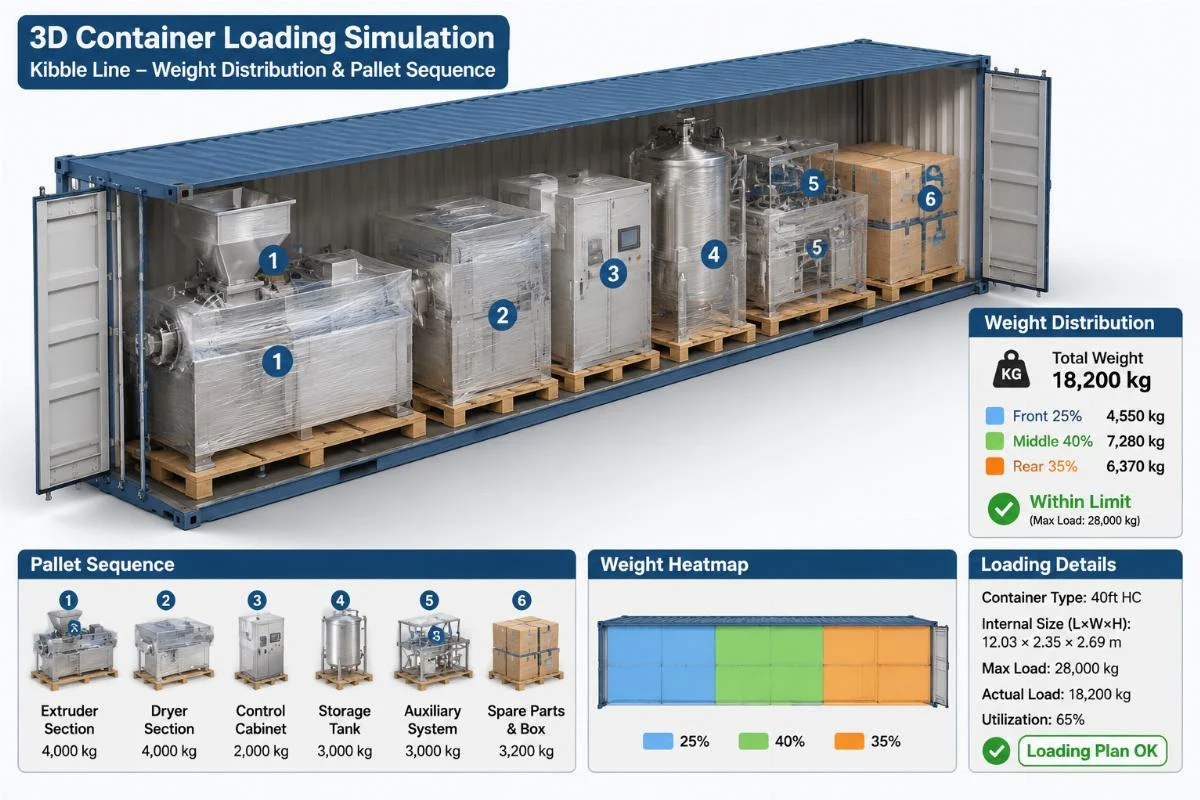
Let us break down the exact methodology behind a flawless kibble line shipping process.
Why is 3D Loading Planning Crucial for Kibble Lines?
A 3D loading plan prevents catastrophic equipment deformation and eliminates unboxing chaos on the installation day.
When dealing with a turnkey extrusion setup, the components vary wildly in shape, density, and fragility. The twin-screw extruder core is extremely dense, while the multi-section cooling and coating conveyors are long, hollow, and highly susceptible to torsion. Relying on mental math or basic 2D sketches inevitably leads to severe weight imbalances. During ocean transit, a vessel encounters dynamic pitching and rolling. Without a calculated 3D simulation, the heavy extruder barrel might shift, acting as a battering ram against the delicate dryer modules.
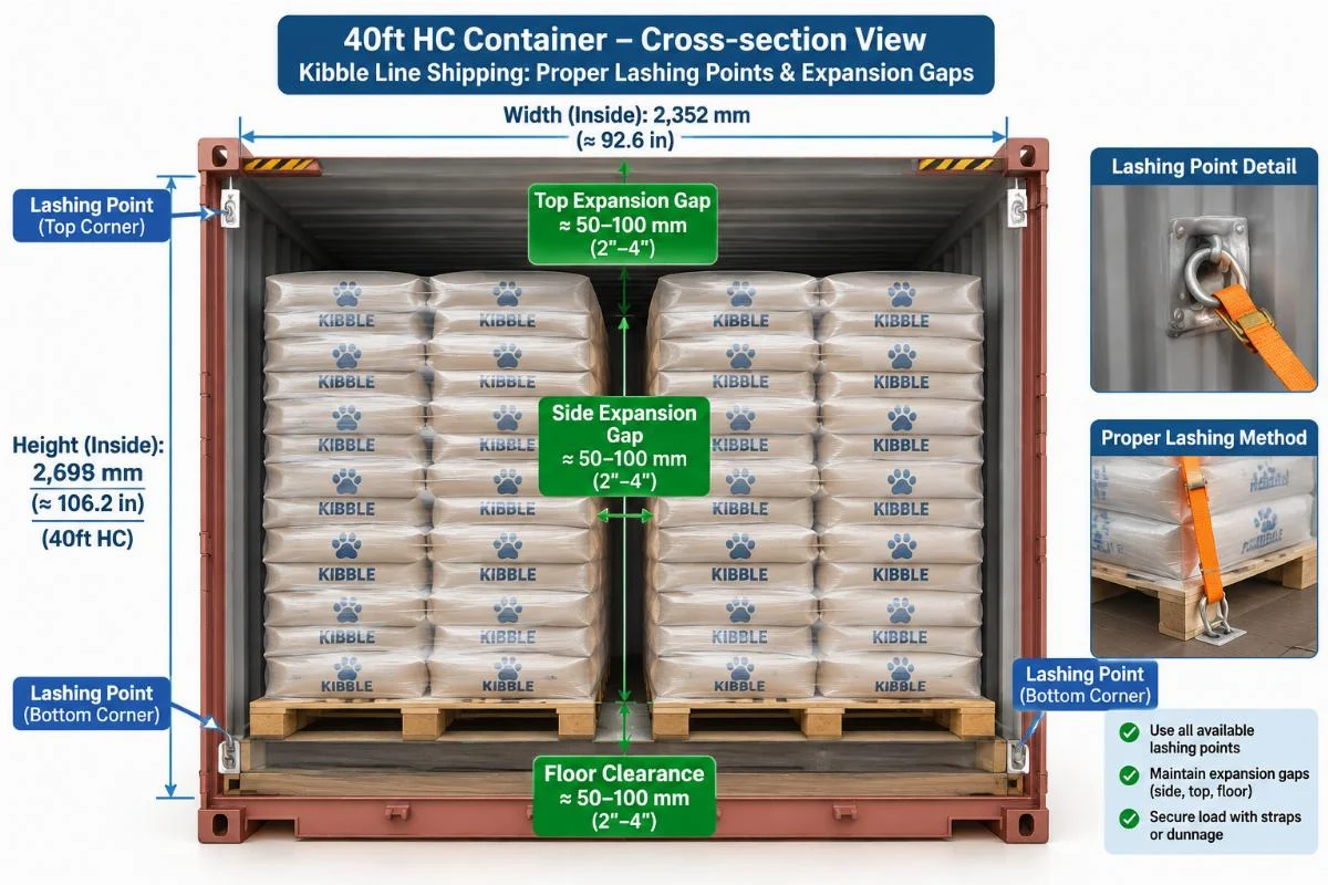
Consider a case where a startup owner in South America received their equipment. The forwarder had simply pushed the crates in to maximize space, leaving zero expansion gaps. The vibration during the voyage caused the wooden crates to splinter inward, damaging the sensitive frequency converters mounted on the main control panel.
Risk Checklist for Poor Planning:
- Torsion Deformation: Long conveyors bending under uneven pressure.
- Impact Damage: Dense components breaking free and striking fragile parts.
- Moisture Intrusion: Improper sealing leading to marine-grade humidity destroying electrical cabinets.
- Installation Delays: Crucial assembly parts buried at the bottom of the container.
By utilizing specialized 3D loading simulation software, we map every single crate’s dimensions and weight, ensuring that the center of gravity remains strictly within the safe longitudinal and lateral limits of the container.
How Do We Pack Different Sections of the Extrusion Line?
Different sections demand entirely different packaging architectures to survive the ocean voyage and facilitate logical unboxing.
You cannot wrap a massive twin-screw extruder the same way you pack a simple belt conveyor. The packaging strategy must align with the physical characteristics of each module and the chronological flow of the installation.
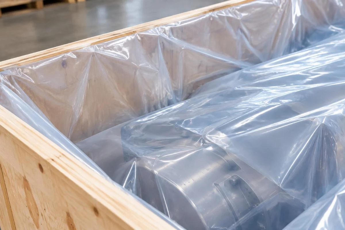
For the core twin-screw extruder and the main dryer modules, we utilize heavy-duty wooden crates with internal moisture-proof barriers. These crates are reinforced with steel brackets to prevent the wood from collapsing under the immense static weight. The marine-grade moisture barrier standards are strictly applied here, as any saltwater intrusion during transit will corrode the precision-machined screw elements and the food-grade stainless steel barrels.
Conversely, the coating drums, cooling conveyors, and vibrating screens are palletized using open wooden frames or heavy-duty steel pallets. These components are wide but relatively lightweight. Wrapping them in fully enclosed wooden boxes would be a waste of container volume and make it impossible to inspect the equipment upon arrival. Instead, they are shrink-wrapped with thick, UV-resistant industrial film, secured tightly to the pallet base to prevent any micro-movements.
Packaging Architecture Matrix:
| Component Category | Primary Packaging | Moisture Protection | Stacking Capability |
|---|---|---|---|
| Extruder & Main Dryer | Reinforced Wooden Crate | Marine-grade Barrier | Non-stackable |
| Coating & Cooling Drums | Open Wooden Frame | Industrial Shrink Wrap | Stackable (with dunnage) |
| Control Cabinets | Plywood Enclosure | Desiccant & VCI Film | Non-stackable |
| Pipes & Small Parts | Cardboard Boxes on Pallet | Standard PE Wrap | Stackable |
This differentiated approach ensures that the heavy, critical components are shielded from impact, while the bulky, lightweight sections are secured efficiently without wasting valuable cubic meters.
What Are the Weight Distribution Rules for a 40ft HC?
Strict adherence to weight distribution rules prevents container tipping, axle overloading, and catastrophic cargo shift during transit.
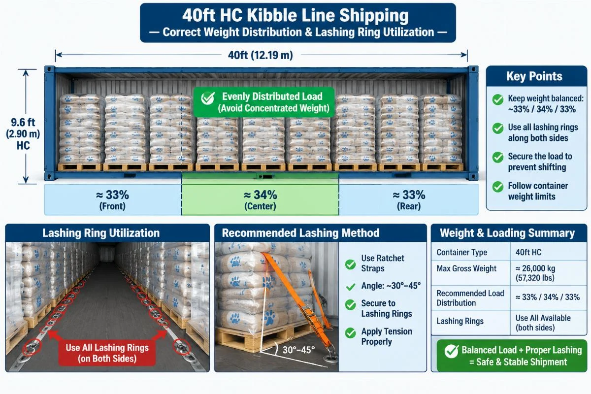
Loading a 40ft HC container is not just about fitting everything inside; it is a complex physics problem. The total weight of a complete mid-scale capacity line can easily approach the maximum payload limit of the container. If the weight is concentrated entirely at the rear doors, the forklift will struggle to extract the cargo, and the truck chassis might experience dangerous axle overload during inland transport. If the weight is concentrated on one side, the container could tip over during a sharp turn on a train or a truck.
The golden rule is to distribute the heaviest items, like the extruder gearbox and the main motor assemblies, evenly across the floor area, keeping the center of gravity as close to the geometric center of the container as possible. We use lashing points distribution ratios calculated specifically for the cargo’s mass. Heavy machinery must be bolted or heavily lashed to the container’s internal lashing rings using high-tensile steel wire ropes and heavy-duty ratchet straps.
Furthermore, we never ignore the importance of dunnage. Airbags and timber bracing are inserted into the void spaces between pallets. This is not merely to stop the cargo from sliding; it is to eliminate the kinetic energy buildup that occurs when the vessel brakes or accelerates. A common misconception is that tight packing is enough. In reality, without proper friction and bracing, tightly packed wooden crates can still grind against each other, generating enough force to snap the crate corners.
How Does Palletizing Sequence Affect On-Site Installation?
The palletizing sequence must mirror the exact on-site installation flow to prevent days of frustrating container reorganization.
Imagine arriving at your factory, eager to start assembling your new pet food production line, only to realize that the critical connecting pipes and the main control cabinet are buried at the very back of the container, behind tons of heavy cooling conveyors. You would have to unload half the container, move the cargo to a temporary warehouse, and then bring it back in the correct order. This turns a streamlined installation into a logistical nightmare, costing you extended service life meaningfully in terms of project timelines and labor expenses.
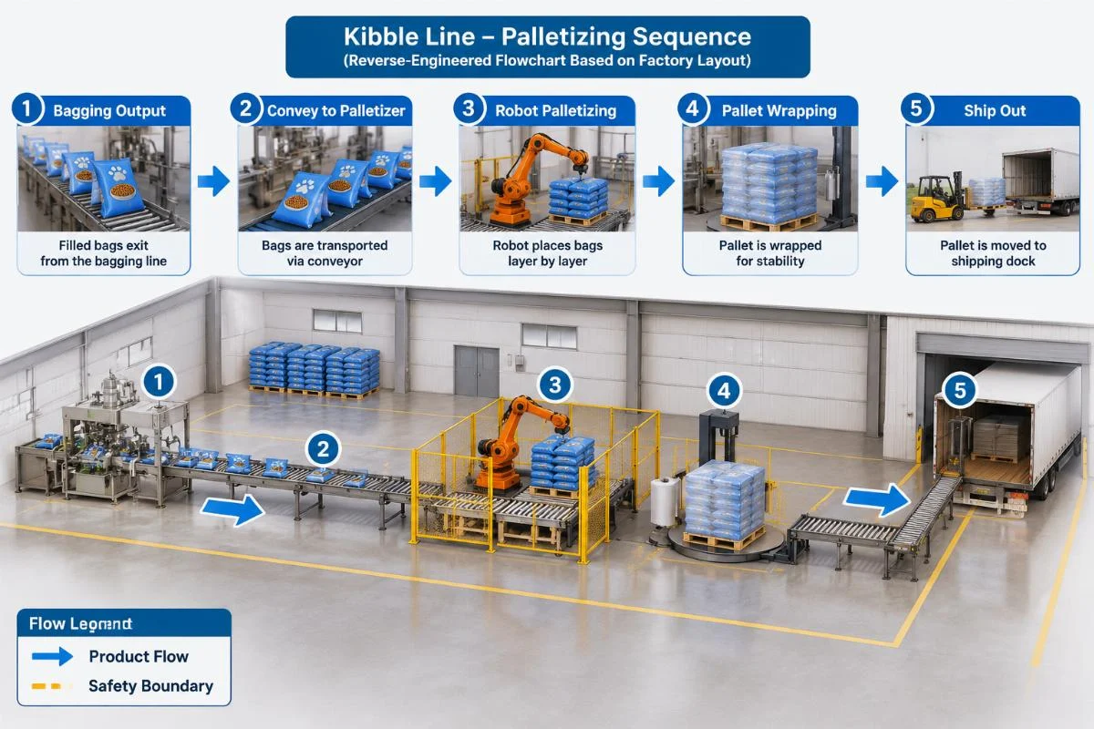
To prevent this, we reverse-engineer the loading plan based on the installation blueprint. The components that need to be positioned first—usually the main extruder base, the primary dryer框架, and the core electrical cabinets—are loaded last, meaning they are placed right behind the container doors. They are the first things you see and access when you break the seal.
The subsequent sections, such as the multi-section palletizing for the coating and cooling lines, are loaded in the exact reverse order of their physical layout on your factory floor. This ensures a continuous, linear unboxing process. The workers simply pull each pallet out of the container and place it directly into its designated footprint on the foundation.
This meticulous planning directly reduces client setup time and risk. When a European startup owner received their turnkey line, they praised the fact that the unboxing sequence matched their assembly flow perfectly. They did not have to hire extra forklifts to shuffle the cargo around the yard. The precise shipping directly translated into a faster commissioning phase and immediate production startup.
Conclusion
Flawless kibble line shipping is an engineering discipline, not an afterthought.
Treating the logistics phase with the same rigor as the mechanical design ensures that your investment arrives intact, balanced, and ready for immediate assembly. By prioritizing 3D loading simulations, differentiated packaging architectures, strict weight distribution, and installation-mirrored palletizing, you eliminate transit risks and accelerate your path to profitable production.
Machines Mentioned in This Article

cat food machine
Dog Food Extruder Machine Manufacturer for Pet Food Kibble Making Line
View Machine
cat food machine
Pet Food Processing Equipment Plant Manufacturer Dog Food
View Machine
cat food machine
Dry Dog Food Production Line Pet Food Pellet Machine
View Machine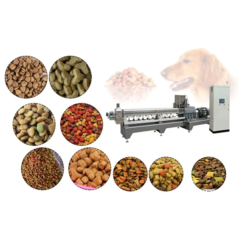
cat food machine